|
|
| PJRC.COM Offline Archive, February 07, 2004 Visit this page on the live site |
| ||
|
Shopping Cart
|
| Home | MP3 Player | 8051 Tools | All Projects | PJRC Store | Site Map |
|
You are here:
8051 Tools
| Search PJRC |
|
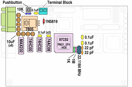
The diode, electrolytic capacitors, and ICs are polarity sensitive and must be inserted ash shown in Figure 1. Shorter components (resistors and the diode) should be soldered before the taller components are inserted. Table 1 lists reasonable order for the assembly of step #1.
 |
| Figure 1: Component Placement for Step 1 (Minimal System) |
| ||||||||||||||||||||||||||||||||||||||||||||||||||||||
| Table 1: Parts List for Step 1 (in approximate order for easiest assembly) |
The 87C52 processor must be programmed with "PM21_2F4.HEX". If you purchased the unassembled kit or a preprogrammed chip from PJRC, then the code is already written. If your chip is blank, you will need to buy or borrow an EPROM programmer which is capable of writing to the 87C52.
If you are using your own components (rather than an unassembled kit from PJRC), many of the components may be substituted with similar parts if you do not have the exact values. The crystal may be any frequency from 4 to 24 MHz, though certain values such as 11.0592 or 22.1184 MHz will allow high speed baud rates and are therefore preferable. The 87C52 oscillator is uses the crystal in "parallel resonance" mode, but a "series" type crystal may be substituted with a small error in the actual frequency (perhaps important to know for some timing-critical applications). Resistor values and the 10 µF capacitors are not critical and similar parts may be substituted (e.g a 4.7 µF capacitor should work).
Connect a five volt power supply to the board. The voltage must be between 4.5 to 5.5. The 12 volt input on the board is not required, and it's a good idea to leave it unconnected until it is needed.
Once the terminal program is running, turn on the power to the board. One or two random characters may appear on the computer's terminal window as the power is turned on. PAULMON2 waits for you to send a carriage return character after the power is turned on (so it can detect your baud rate setting). Press Enter and you should receive the PAULMON2 welcome message:
               Welcome to PAULMON2 v2.1, by Paul Stoffregen

  See PAULMON2.DOC, PAULMON2.EQU and PAULMON2.HDR for more information.


Program Name                     Location      Type
  List                             1000      External command
  Single-Step                      1400      External command
  Memory Editor (VT100)            1800      External command

PAULMON2 Loc:2000 >
|
If you did not receive this welcome message you pressed Enter, then it's time to start troubleshooting.
You will probably want to use the board at a faster baud rate. If you are using the 22.1184 MHz crystal supplied by PJRC, then you can use 115200 baud, and all other standard baud rates down to 1200 baud (300 baud is too slow for the 8051's timer1 with a 22.1184 MHz crystal). If you are using a different crystal, particularly on that is not chosen to allow high speed baud rates, your maximum baud rate will be much slower.
PAULMON2 stores the current baud rate information in the 8051's volatile internal RAM, so that it can skip the baud rate detection (waiting for you to press Enter) if the baud rate is already known. The downside to this is that you must remove power for a long enough time that the 8051's internal memory is cleared. Usually 5-10 seconds is enough time. When you restart from the power removed, PAULMON2 will wait for Enter to detect the baud rate. You must completely remove power each time you change the baud rate on the PC, so that PAULMON2 doesn't reboot and use the old baud rate while your PC is set to the new one (resulting in lots of "garbage" characters on the screen).
When you're ready to begin soldering again, proceed to the next step where you will gain the ability to download your own programs to the board and run them.
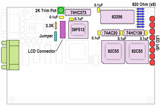
The LEDs are polarized and will not function if they are installed incorrectly. Each LED has a flat side, which is aligned with the edge of the board. As before, all of the chips are polarity sensitive and must be installed as shown in figure 2.
 |
| Figure 2: Component Placement for Step 2 (Memory and Peripherals) |
| |||||||||||||||||||||||||||||||||||||||||||||
| Table 2: Parts List for Step 2 (in approximate order for easiest assembly) |
Begin ascii transfer of Intel hex file, or ESC to abort.
Then you must send the ex1_2.obj file to PAULMON2. Most terminal
emulation programs call this ASCII Upload or some similar name.
Hyperterminal uses "Send Text File..." in the "Transfer" menu.
The text that appears on the screen should look like this:
PAULMON2 Loc:2000 > Download Begin ascii transfer of Intel hex file, or ESC to abort ................................. Download completed Summary: 33 lines received 505 bytes received 505 bytes written No errors detected |
In most cases where the RAM is not working properly, an error about "Unable to write" should appear. Other types of errors, such as checksums, unexpected hex digits, etc usually indicate problems with the download process. If you do get any errors or the download process doesn't appear as shown above, go to the troubleshooting page.
In this example, EX1_2.OBJ was used. The other files are assembled at 4000 and 8000, which will use another part of the RAM or the Flash ROM. If you wish to try these, you will need to select their address to jump to them, instead of 2000 as shown.
Once the program has downloaded successfully, you can run it with the JUMP command (press "J"). The memory location to jump to should be 2000, and it will probably be the default location.
The EX1_2.OBJ program will prompt you to enter a string. Here is an example when "PAULMON" is typed:
Please type a word (9 char max): PAULMON ###### # ## ## ## ## ## ##### ## ## ####### ### ## ## ## ### ### ####### ### ## ## ## ### ## ## ## ####### ## ## ### ## ## ## ## ## ## ## ## ## # ## ## ## #### ## ####### ## ## ## ## ## ## # ## ## ## ## # ## ###### ##### ## ## ## ## ## ## ## ## #### ## ####### ## ## ## ## ## ## ## ## ### ## ## ## ####### ####### ## ## ####### ## ## ## ## ## ##### ####### ## ## ##### ## ## Press any key |
If this message appears only briefly and then the system restarts, it is probably a sign that your terminal emulation software is configured to send CR/LF when you press Enter. If this is the case, it should be set to only send CR (ascii code 13).
At this point, you can download programs to your board. You may want to try writing a few simple programs, perhaps by copying and pasting bit of code from the EX1.ASM program. This program, like PAULMON and the examples in the code library, is in the public domain, so you can use whatever parts you find useful in your own programs. It may also be helpful to look over the PAULMON2 Documentation.
The 82C55 chips and LEDs can be tested using the LED Blink example code, which is also available in C instead of assembly. These pages also illustrate the usage of the assembler and C compiler, which should get you started toward writing your own application using these languages.
