|
|
| PJRC.COM Offline Archive, February 07, 2004 Visit this page on the live site |
| ||
|
Shopping Cart
|
| Home | MP3 Player | 8051 Tools | All Projects | PJRC Store | Site Map |
|
You are here:
MIDI Drum Machine
| Search PJRC |
|

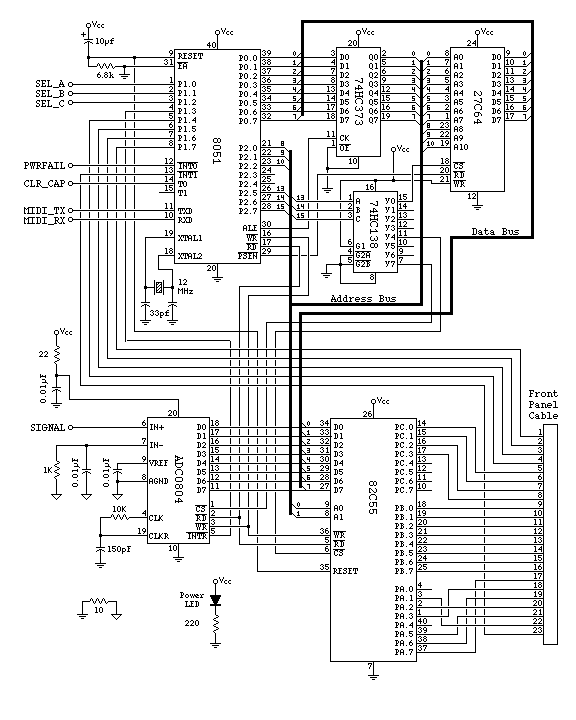
TODO: add some explaination about what these chips do, and hopefully that text will have links to the other schematics.
TODO: describe pinouts of the 23 conductor ribbon cable.
TODO: The EPROM is a 28C16 (27C16 will also work). The 27C64 is an error. The pin numbers shown should be correct for the 24 pin 28C16, not the 28 pin 27C64.
TODO: Does it really work with the simple R-C reset circuit. We had a lot of trobule with that, and went to a few different circuits. What was the reset circuit that finally ended up in the working unit.
TODO: The 82C55 chip select (pin 6) is actually connected to pin 10 on the 74HC138 chip, not pin 11 as shown. Need to fix the schematic image.
TODO: Create a page with a complete parts list
Other Schematics:
Note: This schematic is where most of the changes are planned for a new board. The 82C55 and 7 segment decoders on the display board will be changed to a group of shift registers on the display board, so that the 82C55 and the large number of wires won't be needed. The ADC0804 will be replaced with a serial interface ADC chip, and the 8051 will be replaced with a 89C51, so that the 27C16, 74HC373 and 74HC138 won't be needed. The main idea is to greatly reduce the number of wires, so that people who attempt to build the design without a printed circuit board will have far fewer wires to interconnect, and most wiring errors will result in only a portion of the drum machine not working, instead of having the entire thing dead and no reasonable way to troubleshoot. The new board will also only require a single 5 volt supply and will use an inexpensive EEPROM chip instead of battery backup.
| PJRC Home | Site Map | Technical Projects | MIDI Drum Main Page |