|
|
| PJRC.COM Offline Archive, February 07, 2004 Visit this page on the live site |
| ||
|
Shopping Cart
|
| Home | MP3 Player | 8051 Tools | All Projects | PJRC Store | Site Map |
|
You are here:
MIDI Drum Machine
| Search PJRC |
|

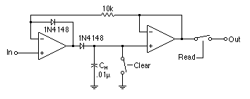
This circuit is a track and hold. The idea is that the input waveform may reach a peak at any instant as the drummer strikes the pad. When that occurs, the capacitor is charged to the peak input voltage. There is only one A/D converter (ADC0804, see the Main CPU section schematic), and it takes time for it to convert an input voltage to a 8-bit code. No matter when the drummer strikes the pad, the capacitor will "remember" the peak input voltage, so that it can be read later as the A/D convert cycles through the 8 inputs.
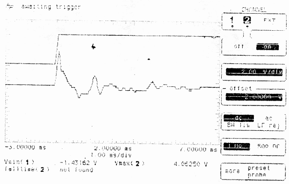
This plot shows the track and hold cirucit in action. The lower waveform
is the raw input from the pad's transducer, and the upper waveform is
the output which will be read by the A/D converter at some later time.

The two switches shown are actually CD4051 8:1 analog MUX chips (see the Complete Analog Schematic. The one labeled Read connects one of the 8 inputs to the A/D converter. After the A/D converter is finished, the CPU briefly closes the Clear switch to discharge the capacitor. This is necessary because the peak tracking behaviour will only increase the voltage on the capacitor. The opamps are LM324 (PNP inputs), so the leakage current from the input transistors will also slowly increase the voltage on the capacitors. Clearing the capacitor's charge after every sampling prevents any false readings.
Other Schematics: