|
|
| PJRC.COM Offline Archive, February 07, 2004 Visit this page on the live site |
| ||
|
Shopping Cart
|
| Home | MP3 Player | 8051 Tools | All Projects | PJRC Store | Site Map |
|
You are here:
MP3 Player
| Search PJRC |
|

The two pin connector next to the IDE ports is intended to allow the board to run from four AA size batteries. It can also accept a 5 volt power input.

A three pin connector is located close to the left line-level audio output. This connector allows an alternate 12 volt input, which is connected directly to the main power jack. The IDE Disable pin, when pulled low, requests that the board's IDE interface place all of its IDE signals into a high impedence mode (tri-state). Note, currently (13 Sep 2000) this feature is not implemented by the firmware.

The four pin connector near the right side of the SIMM socket is intended to allow a LCD display board to be connected. The transmit and receive are connected to the same UART as the serial port connector.

TODO: Diagram
TODO: Photo
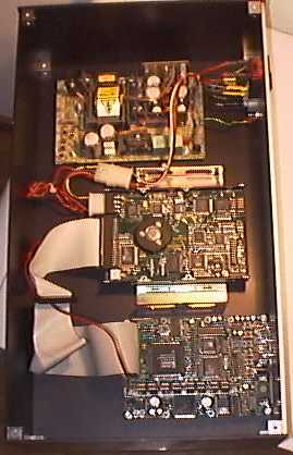
Patrick Fischer sent a photo of his board mounted in a black 42cm case that matches other stereo components, available from from Thel (German site). The power supply provides power directly to the standard size hard drive, and the +5 volt line and group run to the 4.5-6 volt input on the MP3 player board.
 |
| MP3 Player Board Mounted in Enclosure, by Patrick Fischer |
The red line (+5 volts) is attached to the positive side of the large 2200 µF capacitor on the right side. The black wire (ground) is connected to the negative size of this capacitor. The orange wire (+3.3 volts) is connected to the positive side of either of the 330 µF capacitors directly above the large capacitor.
TODO: Diagram
TODO: Photo
Warning: the current firmware (13 sep 2000) operates the drive continuously, and the pre-regulator can become hot. Please check the temperature of the transistor on the right side of the board, to make sure that is is cooling adaquetely. Future firmware will use DRAM buffering and never operate the drive in a high power mode for more than several seconds.
TODO: Diagram
TODO: Diagram