|
|
| PJRC.COM Offline Archive, February 07, 2004 Visit this page on the live site |
| ||
|
Shopping Cart
|
| Home | MP3 Player | 8051 Tools | All Projects | PJRC Store | Site Map |
|
You are here:
8051 Tools
| Search PJRC |
|
The description here assumes you are familiar with how to communicate with the 8051 development board and download and run programs on it. If you haven't done this yet, the Using The Board For The First Time page explains in detail exactly how to setup communication with the board and download programs to it and run them.
Of course, you need to download the LED Blink AS31 source code:
The LED blink program comes with a copy already assembled, as "blink.hex". It is 10 lines of text, 398 bytes, or 408 bytes if converted to DOS CR/LF text format.
You should download this copy to the board and run it. You may use "Jump" to "2040", or use the "Run" command and select it from the menu, since this program has the 64 byte header that allows PAULMON2 to recognize it. Figure 1 illustrates what you should see when you run the LED blink program.
|
Figure 1: LED Blink Example Program |
The blink program checks for you to press ESC as it is running, and aborts when it sees ESC. When you run other programs which run in an infinite loop and don't abort, press the reset button (located next to the serial port) to reboot the board. If no auto-start programs are in memory, you will be returned to PAULMON2. When you later load auto-start programs into the flash, you will need to use the "ERASE FLASH" jumper to return to PAULMON2.
Using your favorite text editor, load the BLINK.ASM file, and make a change. Find the code that causes a delay between each update to the LEDs. It looks like this:
        ;delay for a number of ms (specified by acc)
delay:
        mov     r0, a
dly2:   mov     r1, #230
dly3:   nop
        nop
        nop                     ;6 NOPs + DJNZ is 4.34 us
        nop                     ;with the 22.1184 MHz crystal
        nop
        nop
        djnz    r1, dly3        ;repeat 230 times for 1 ms
        djnz    r0, dly2        ;repeat for specified # of ms
        ret
|
This code waits for a length of time, which is set by the value of the accumulator when it is called. There are two nested loops. By changing the number "230" to something smaller, the delays will be shorted and the blinking animation will run more rapidly. For example, you could change this to 76 to make the display animate 3 times faster. Once you've made your changes, run AS31 to produce a new intel-hex file to download.
To run AS31, you just type:
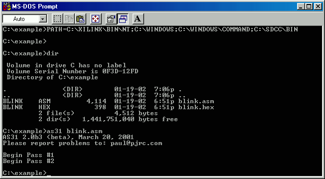
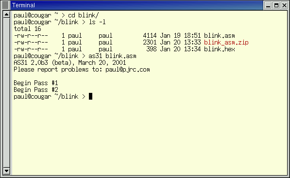
as31 blink.asmWindows users will usually run AS31 in a "MS-DOS Prompt" window, as shown in figure 2. Linux distributions usually provide many terminals and shells. Figure 3 shows AS31 run from the Gnome Terminal, which is the default provided by Red Hat Linux 7.1.
If AS31 is installed properly, it will run as shown and produce a new intel hex output file. When you download this new .hex file to your board and run it, the faster animation should be very easy to see.
AS31 is also available with a GTK-based GUI front end when build on linux-based systems. To run the GUI version, type "as31-gtk".

Figure 2: Using AS31 (Windows/MS-DOS Prompt), To Assemble BLINK.ASM |

Figure 3: Using AS31 (Linux/Gnome Terminal), To Assemble BLINK.ASM |
The blink program uses a simple lookup table, which you can easily modify for different blinking patterns. In the lookup table, each pattern is shown and each has a time delay value. The last entry of the table has a time delay of zero, which marks the end of the list and causes the program to begin again at the top. Here's the lookup table from the code:
table:  .db     01111111b, 90
        .db     00111111b, 70
        .db     00011111b, 50
        .db     10001111b, 40
        .db     11000111b, 40
        .db     11100011b, 40
        .db     11110001b, 40
        .db     11111000b, 50
        .db     11111100b, 70
        .db     11111110b, 90
        .db     11111100b, 70
        .db     11111000b, 50
        .db     11110001b, 40
        .db     11100011b, 40
        .db     11000111b, 40
        .db     10001111b, 40
        .db     00011111b, 50
        .db     00111111b, 70
        .db     255,0
|
By changing the bit patterns and delays, together with removing or adding more lines, you can make this simple LED blink program produce nearly any blinking display that cycles through a fixed set of states.
The boards that are tested by PJRC have a copy of this LED blink test loaded in the flash memory. To configure where a program will be loaded, you would edit the first line. The first line of the file should be:
.equ locat, 0x2000 ;Location for this program |
To cause it to be loaded into the flash memory, set the location between 0x8000 to 0xFF00 (the last two digits must be zero for PAULMON2 to recognize the header). To program the flash memory, download your program in the same way as loading it into RAM, and PAULMON2 will automatically handle the flash programming as it receives the data. The portion of flash memory where you're downloading must be erased, otherwise the download will not work and you'll see errors reported. Because the ram doesn't need to be erased before it is written, it's easier to develop your code by downloading it into the RAM, and then setting it to the flash when it's working.
If you want to make the board run this LED blink program without being attached to your PC, edit the header to tell PAULMON2 that this is a startup program. To do this, change the "35" to "249" in the header. More details can be found in the PAULMON2 manual. Once you've done this, the board will boot up and run the LED blink instead of PAULMON2. To get back to PAULMON2, short the "ERASE FLASH" jumper and press the reset button.
Hopefully this page has provided you with a simple easy-to-get-going example with AS31 and the 8051 development board.