 |
|||||
How to use LIN? |
June 28, 2004 |
||||
Motorola, the semiconductor specialists from the seven founding companies of LIN, produces many microcontrollers for LIN Slave and LIN Master applications. (Click here to view a product listing.) Recently in 2003, Motorola released an application report showing the basic design and implementation of one way to implement a closed-loop control position servo motor utilizing the Local Interconnect Network. (Click here) The use of the LIN can allow a series of similar motors to be networked together and controlled from a central LIN Master controller. Specifically, the document addresses a set of servo motors in an automotive HVAC system connected to a LIN network.
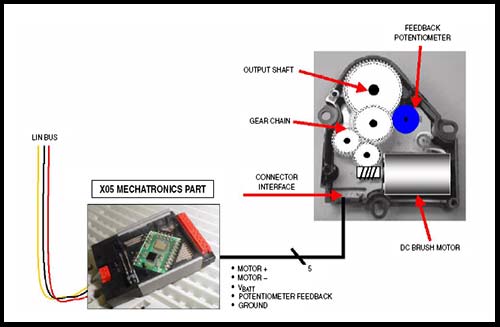
In the above Figure, we see the use of a Motrola X05 with a built-in 8-bit HC08 microcontroller as a LIN Slave controller. The servo (above right) consists of a DC powered Brush Motor connected to a gear chain. The output shaft of the actuator is about 950 times slower that the motor shaft, allowing slow, precise movement. The movement is also measured and feedback is given by use of a potentiometer. This allows the motor to move something to a desired location. This type of application in an automotive HVAC system is often seen in internal vent control. Other places one might see this type of LIN application would be in mirror positioning, seat positioning, power locking and trunk mechanisms, windshield wiper motors, power sliding sunroof, headlight positioning, etc... The motorola application showcases a closed-loop design. To understand a closed-loop design, one must first look at an open-loop system. An open-loop system is often referred to as a "fire and forget" approach to control. The LIN Master may send a stimulis to the controller which commands the system to go to a particular location, speed, whatever. The hope is that the system responds accordingly. However, there is no guarentee that the system even received the command, much less acted upon it. The key to a closed-loop control system is the introduction of feedback. For instance if speed were being controlled, feedback may consist of a measure of the current speed. This would allow for adjustment accordingly. After realizing that a closed-loop design may be better for a particular application, knowing where to close the loop is the next challenge. The loop can either be closed at the load itself, or through the network. Many deciding factors take place when attempting to determine this including required performance, network speed and achitecture, system level cost, and the number of motors to be controlled throughout the network. In our case of the HVAC system, it might first seem best to close the loop through the network. The response times are slow, and it would greatly simplify the actuator design. However the problem here lies within the system design. An autmobile manufacturer may wish to have three, four, or even more levels of complexity for the HVAC system depending on the model of vehicle. For each vehicle plaform, there may be different features. One design may simply have an on/off structure, while another may have seperate zone climate control or oscilating vents. If the control loop were closed through the network, then response times for each node would increase with the number and complexity of the nodes. Just as well, different messaging and programming would be required for each system, inventories would have to be kept of all different variations, and software would have to be maintained for each variation. A simpler and more cost-effective means would be to close the loop locally at each controller node. This network strategy would allow the car manufacturer to use one strategy for all of their vehicle lines. Next in things to do would be to choose a logical messaging strategy. Since the HVAC system is fairly simple it may first seem simple to define a messaging strategy. The challenge here does not come into play with complexity, but instead with cost-efficiency. By utilizing the LIN system, there is one master with a stable timeing base. The slave nodes however can have much lower tolerances on clocking and are simple enough to implement in a variety of mechatronic and microcontroller solutions. In order to use these inexpensive and simple devices, the messaging system should be as simples and straightforward as feasibly possible. In our case with a servo motor, the main messaging functions needed include an input command (a desired location to goto by the servo), a node status request command (a request for the current position, current command being acted on, power load diagnostics, and LIN messageing error codes), and a NVM Programming command (to upload new softare to the node from the master). Basic control of the system would intially come from a LIN Master device. The LIN Master would send an input command to the LIN Slave. The LIN Slave would then process the command and being moving the servo to the desired location. The LIN Slave would use feedback to control the direction, speed, and ultimately when to stop. If any errors occur, the LIN Slave controller would attemp to resolve them itself. Ultimately the LIN Master would send a node status request command to determine if the event was a success, a failure, or is still in progress. The application report from Motorola goes into further detail on system and code design which will not be discussed here. However the point is clear on how the application described can be implemented using a Local Interconnect Network, and further how it could be implemented for many types of specific applications. For further information on Motorola LIN Solutions and for more reports on specific applications, I would recommend checking out FreeScale semiconductor's application notes page (Click here). FreeScale is a semiconductor firm launched by Motorola.
|
|||||
How to use LIN? |
John Richardson 06/28/04 |
||||